
3D Printed Boost tube Proof of Concept
I own and drive a 1990 Volkswagen Corrado. This car comes from the factory with a 1.8L supercharged engine. Following a mod to the charger that increased the laminar nature of the air flow and eliminated the nearly useless silencer box, I encountered a problem. The problem involved an offset tube to go around the radiator, a part available in a $400 custom tube set.
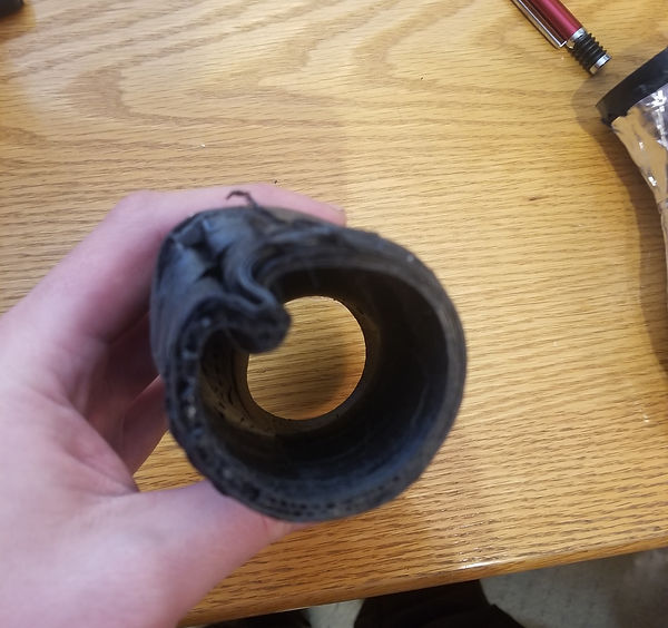
That is when I turned to 3D printing. I decided to try to replace the boost tube with a 3D printed one. My first attempt used flexible TPU filament to replicate the rubber tubing in place. The proved to be a failure, the TPU does not do a good job of holding pressure. The next try used PLA. The Picture 1 shows what the first version looked like post vehicle test. PLA does print well and quickly, and holds pressure well. It does not hold up to engine bay ambient heat well though, as seen in Picture 2 and deformed and popped off. I turned to PETG, and revamped the modeling. Picture 3 shows version two test printed in PLA. I had some PETG problems including extrusion issues because I did not have the all metal hotend mod installed. I also had a weird sidewall failure seen in Picture 3. Picture 4 shows the heat deforming that occurred with hose clamp pressure applied in the bay. Picture. 5 and 6 show the rubber coating an aluminum tape that I used to seal any micro holes in the sidewall, and well as provide insulation against further heat damage. Picture 6 is like the version currently been road tested in the car. The version in my car is printed at slow speeds at 255c and .04 layer height for 72 hours. This has lasted several trips the longest any tube has lasted so far.


Picture 1 : Right angle design
Picture 2: PLA Heat warp under hose clamp force.
Picture 3 Swept design PETG with rubber coating
Picture 4: Strange Failure after Hard Pull
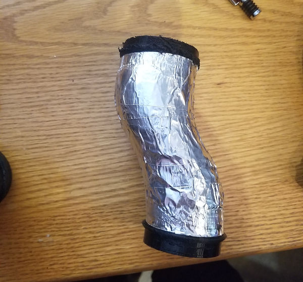
Picture 5: Final Version
As can be seen in the pictures above, I made some modifications to the design. In Picture 3 you see the final shape of the tube, more swept for better air flow. In Picture 5, it the version currently in the car. I reduced the layer height to .04mm in order to improve layer adhesion failure as seen in Picture 4. I also increased the wall thickness starting just after the mounting ridges for the tubes. This helps prevents further wall failures. Then I sealed the porous plastic in spray rubber to make air tight, and then wrapped in aluminum tape to provide heat reflection. Please see the table below for the test data and runs I have made in various places to fully test the replacement.